Archive for the ‘Papers’ Category
Cloud-to-ground lightning bolts are a common phenomenon—about 100 strike Earth’s surface every single second—yet their power is extraordinary. Each bolt can contain up to one billion volts of electricity.
This enormous electrical discharge is caused by an imbalance between positive and negative charges. During a storm, colliding particles of rain, ice, or snow increase this imbalance and often negatively charge the lower reaches of storm clouds. Objects on the ground, like steeples, trees, and the Earth itself, become positively charged—creating an imbalance that nature seeks to remedy by passing current between the two charges.
A step-like series of negative charges, called a stepped leader, works its way incrementally downward from the bottom of a storm cloud toward the Earth. Each of these segments is about 150 feet (46 meters) long. When the lowermost step comes within 150 feet (46 meters) of a positively charged object it is met by a climbing surge of positive electricity, called a streamer, which can rise up through a building, a tree, or even a person. The process forms a channel through which electricity is transferred as lightning.
Some types of lightning, including the most common types, never leave the clouds but travel between differently charged areas within or between clouds. Other rare forms can be sparked by extreme forest fires, volcanic eruptions, and snowstorms. Ball lightning, a small, charged sphere that floats, glows, and bounces along oblivious to the laws of gravity or physics, still puzzles scientists.
Lightning is extremely hot—a flash can heat the air around it to temperatures five times hotter than the sun’s surface. This heat causes surrounding air to rapidly expand and vibrate, which creates the pealing thunder we hear a short time after seeing a lightning flash.
Lightning is not only spectacular, it’s dangerous. About 2,000 people are killed worldwide by lightning each year. Hundreds more survive strikes but suffer from a variety of lasting symptoms, including memory loss, dizziness, weakness, numbness, and other life-altering ailments.
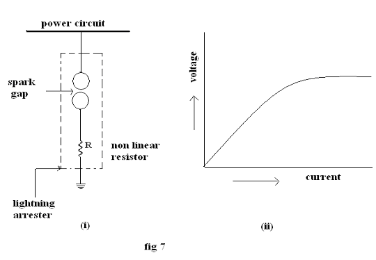
The earthing screen and ground wires can well protect the electrical system against direct lightning strokes but they fail to provide protection against travelling waves, which may reach the terminal apparatus. The lightning arresters or surge diverters provide protection against such surges. A lightning arrester or a surge diverter is a protective device, which conducts the high voltage surges on the power system to the ground
Fig 7(i) shows the basic form of a surge diverter. It consists of a spark gap in series with a non-linear resistor. One end of the diverter is connected to the terminal of the equipment to be protected and the other end is effectively grounded. The length of the gap is so set that normal voltage is not enough to cause an arc but a dangerously high voltage will break down the air insulation and form an arc. The property of the non-linear resistance is that its resistance increases as the voltage (or current) increases and vice-versa.
The action of the lightning arrester or surge diverter is as under:
(i) Under normal operation, the lightning arrester is off the line i.e. it conducts no current to earth or the gap is non-conducting
(ii) On the occurrence of over voltage, the air insulation across the gap breaks down and an arc is formed providing a low resistance path for the surge to the ground. In this way, the excess charge on the line due to the surge is harmlessly conducted through the arrester to the ground instead of being sent back over the line.
(iii) It is worthwhile to mention the function of non-linear resistor in the operation of arrester. As the gap sparks over due to over voltage, the arc would be a short-circuit on the power system and may cause power-follow current in the arrester. Since the characteristic of the resistor is to offer low resistance to high voltage (or current), it gives the effect of short-circuit. After the surge is over, the resistor offers high resistance to make the gap non-conducting.
TYPES OF LIGHTNING ARRESTERS
There are several types of lightning arresters in general use. They differ only in constructional details but operate on the same principle viz, providing low resistance path for the surges to the round. Following are the different types of lightning relays:
1. Rod arrester 2.Horn gap arrester
3. Multigap arrester 4. Expulsion type lightning arrester
5. Valve type lightning arrester
A lightning arrester is a device used on electrical power systems to protect the insulation on the system from the damaging effect of lightning. Metal oxide varistors (MOVs) have been used for power system protection since the mid 1970s. The typical lightning arrester also known as surge arrester has a high voltage terminal and a ground terminal. When a lightning surge or switching surge travels down the power system to the arrester, the current from the surge is diverted around the protected insulation in most cases to earth.
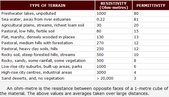
Soil resistivity is a function of soil moisture and the concentrations of ionic soluble salts and is considered to be most comprehensive indicator of a soil’s corrosivity.
Corrosivity ratings based on soil resistivity
Since ionic current flow is associated with soil corrosion reactions, high soil resistivity will arguable slow down corrosion reactions. Soil resistivity generally decreases with increasing water content and the concentration of ionic species. Sandy soils are high up on the resistivity scale and therefore considered the least corrosive. Clay soils, especially those contaminated with saline water are on the opposite end of the spectrum.
Field soil resistivity measurements are most often conducted using the Wenner four-pin method and a soil resistance meter. The Wenner method requires the use of four metal probes or electrodes, driven into the ground along a straight line, equidistant from each other, as shown in the following Figure. Soil resistivity is a simple function derived from the voltage drop between the center pair of pins, with current flowing between the two outside pins.
Wenner four pin soil resistivity test set-up
An alternating current from the soil resistance meter causes current to flow through the soil, between pins C1 and C2. The voltage or potential is then measured between pins P1 and P2. The meter then registers a resistance reading. Resistivity of the soil is then computed from the instrument reading, according to the following formula:
where:
ρ is the soil resistivity (ohm-centimeters)
A is the distance between probes (centimeters)
R is the soil resistance (ohms), instrument reading
π equals 3.1416
The resistivity values obtained represent the average resistivity of the soil to a depth equal to the pin spacing. Resistance measurements are typically performed to a depth equal to that of the buried system (pipeline) being evaluated. Typical probe spacing is in increments of 0.8 m (2.5 ft).
If the line of soil pins used when making four-pin resistivity measurements is closely parallel to a bare underground pipeline or other metallic structure, the presence of the bare metal may cause the indicated soil resistivity values to be lower than it actually is. Because a portion of the test current will flow along the metallic structure rather than through the soil, measurements along a line closely parallel to pipelines should be avoided.
When making soil resistivity measurements along a pipeline, for example, it is good practice to place the line of the pins perpendicular to the pipeline with the nearest pin at least 4.5 meters from the pipe or even further, if space permits. Soil resistivity data taken by the four-pin method should be recorded in tabular form for convenience in calculating resistivity and evaluating results obtained. The tabular arrangement may be as shown here.
Format for recording soil resistivity measurements
With experience, much can be learned about the soil structure by inspecting series of readings to increasing depths. The recorded values from four-pin resistivity measurements can be misleading unless it is remembered that the soil resistivity encountered with each additional depth increment is averaged, in the test, with that of all the soil in the layers above. The indicated resistivity to a depth equal to any given pipe spacing is a weighted average of the soils from the surface to that depth. Trends can be illustrated best by inspecting the sets of soil resistivity readings such as in the following example.
The first set of data, Set A, represents a uniform soil conditions. The average of the readings shown (~960 ohm-cm) represents the effective resistivity that may be used for design purposes for impressed current groundbeds or galvanic anodes.
Data Set B represents low-resistivity soils in the first few feet. There may be a layer of somewhat less than 1000 ohm-cm around the 1.5 meters depth level. Below 1.5 meters, however, higher-resistivity soils are encountered. Because of the averaging effect mentioned earlier, the actual resistivity at 2.3 meters deep would be higher than the indicated 1250 ohm-cm and might be in the order of 2500 ohm-cm or more.
Even if anodes were placed in the lower-resistivity soils, there would be resistance to the flow of current downward into the mass of the earth. If designs are based on the resistivity of the soil in which the anodes are placed, the resistance of the completed installation will be higher than expected. The anodes will perform best if placed in the lower resistance soil. The effective resistivity used for design purposes should reflect the higher resistivity of the underlying areas. In this instance, where increase is gradual, using horizontal anodes in the low-resistivity area and a figure of effective resistivity of ~2500 ohm-cm should result in a conservative design.
Data Set C represents an excellent location for anode location even though the surface soils have relatively high resistivity. It would appear from this set of data that anodes located >1.5 meters deep, would be in low-resistivity soil of ~800 ohm-cm, such a figure being conservative for design purposes. A lowering resistivity trend with depth, as illustrated by this set of data, can be relied upon to give excellent groundbed performance.
Data Set D is the least favorable of these sample sets of data. Low-resistivity soil is present at the surface but the upward trend of resistivity with depth is immediate and rapid. At the 2.3 meters depth, for example, the resistivity could be tens of thousands of ohm-centimeters. One such situation could occur where a shallow swampy area overlies solid rock. Current discharged from anodes installed at such a location will be forced to flow for relatively long distances close to the surface before electrically remote earth is reached.
As a result, potential gradients forming the area of influence around an impressed current groundbed can extend much farther than those surrounding a similarly sized groundbed operating at the same voltage in more favorable locations such as those represented by data Sets A and C.
In some areas, experience will show that soil resistivity may change markedly within short distances. A sufficient number of four-pin tests should be made in a groundbed construction area, for example, to be sure that the best soil conditions have been located. For groundbeds of considerable length (as may be the case with impressed current beds), four-pin tests should be taken at intervals along the route of the proposed line of groundbed anodes. If driven rod tests or borings are made to assist in arriving at an effective soil resistivity for design purposes, such tests should be made in enough locations to ascertain the variation in effective soil resistivity along the proposed line of anodes.
In electrical engineering, ground or earth may be the reference point in an electrical circuit from which other voltages are measured, or a common return path for electric current, or a direct physical connection to the Earth.
Electrical circuits may be connected to ground (earth) for several reasons. In mains powered equipment, exposed metal parts are connected to ground to prevent contact with a dangerous voltage if electrical insulation fails. Connections to ground limit the build-up of static electricity when handling flammable products or when repairing electronic devices. In some telegraph and power transmission circuits, the earth itself can be used as one conductor of the circuit, saving the cost of installing a separate return conductor.
For measurement purposes, the Earth serves as a (reasonably) constant potential reference against which other potentials can be measured. An electrical ground system should have an appropriate current-carrying capability in order to serve as an adequate zero-voltage reference level. In electronic circuit theory, a “ground” is usually idealized as an infinite source or sink for charge, which can absorb an unlimited amount of current without changing its potential. Where a real ground connection has a significant resistance, the approximation of zero potential is no longer valid. Stray voltages or earth potential rise effects will occur, which may create noise in signals or if large enough will produce an electric shock hazard.
The use of the term ground (or earth) is so common in electrical and electronics applications that circuits in portable electronic devices such as cell phones and media players as well as circuits in vehicles such as ships, aircraft, and spacecraft may be spoken of as having a “ground” connection without any actual connection to the Earth. This is usually a large conductor attached to one side of the power supply (such as the “ground plane” on a printed circuit board) which serves as the common return path for current from many different components in the circuit.
The general understanding bout lightning protection system for building structure is confined to provision a direct strike lightning air terminal, down conductor and earth terminal.
lightning protection system for building and other associated structure is complete with the following:
1) lightning direct strike air terminal; rods, horizontal copper tape and strip to form mesh or grid like terminal place at roof top.
2) down conductor; the conductor with the purpose to conduct the lightning energy to the ground once the building are struck by lightning.
3) earth terminal; an interface joining the above the ground LPS with the general mass of earth so that there is a solid bond between the LPS with the soil.
4) the equal potential bonding system serve the purpose of making very point of system at the same potential under transient over voltage condition.
5) proper placement and coordination of secondary surge protectors so that at very point on the electrical system, surge protector are installed.
what is the rods which you see in top of buildings?
Posted: February 10, 2011 in Papers, Pictures, VideosA lightning rod or lightning conductor is a metal rod or conductor mounted on top of a building and electrically connected to the ground through a wire, to protect the building in the event of lightning. If lightning strikes the building it will preferentially strike the rod, and be conducted harmlessly to ground through the wire, instead of passing through the building, where it could start a fire or cause electrocution. A lightning rod is a single component in a lightning protection system. In addition to rods placed at regular intervals on the highest portions of a structure, a lightning protection system typically includes a rooftop network of conductors, multiple conductive paths from the roof to the ground, bonding connections to metallic objects within the structure and a grounding network. The rooftop lightning rod is a metal strip or rod, usually of copper or aluminum. Lightning protection systems are installed on structures, trees, monuments, bridges or water vessels to protect from lightning damage. Individual lightning rods are sometimes called finials, air terminals or strike termination devices. The lightning rod was invented by Benjamin Franklin in the Americas in 1749 and, perhaps independently, by Prokop Diviš in Europe in 1754.
pic a is the structure of franklin rod connection and in pic b one rod is illustrated after hit by lightning stroke.
the effect of Franklin rod to protect of Dubai Tower.
— Check for injuries. A person who has been struck by lightning does not carry an electrical charge that can shock other people.
— Provide first aid and call 911 immediately.
— Look for burns where lightning entered and exited the body. If the strike caused the victim’s breathing to stop, give cardiopulmonary resuscitation (CPR) until medical professionals arrive and take over.
Seek safe shelter immediately! If you’re unable to find shelter in a building or residence that is equipped with a lightning protection system, the Lightning Protection Institute suggests the following guidelines:
Indoors
• Stand away from windows, doors, and electrical appliances.
• Unplug appliances well before a storm nears – never during because lightning can follow the wiring.
• Avoid contact with piping, including sinks, baths, and faucets because pipes can conduct electricity.
• Do not use the telephone except for emergencies. People have received severe electrical shocks while using the phone. Cell phones are not a problem.
Outdoors
Look for shelter equipped with a lightning protection system like those found at golf courses, public parks, and pools. If you’re caught outside and unprotected:
• Get in a hard-topped car.• Avoid areas that are higher than the surrounding landscape.
• Never use a tree as a shelter. (If in the woods, find an area protected by a clump of trees; never stand underneath a single tree in the open).
• Keep away from metal objects, including bikes, golf carts, fencing, and machinery, etc.
• Avoid standing near tall objects such as towers, tall trees, fences, telephone lines, or power lines.
• Immediately get out and away from pools, lakes, and other bodies of water.
• Spread out – don’t stand in a crowd of people.
• If you feel a tingling sensation or your hair stands on end, lightning may be about to strike! Immediately crouch down and cover your ears. Do not lie down or place you hands on the ground.
• Victims of lightning shock should be administered CPR and get medical attention.


You must be logged in to post a comment.